Tuesday, March 18, 2014

Arduino–Day 5: 7 Segment Numeral Display


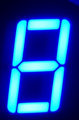
A quick & dirty library for displaying numbers on a 7 Segment Display.  I’m storing the segment patterns in an array at the same position – ordinal - as that of the number.  Thus, a pattern for ‘0’ (Pin 10 & Pin 4 off – Dot & Central bar) would be found at numbers[0].

Countdown on a 7 Seg Display
  1. //Pin patterns for 0-9
  2. int numbers[][8] =  {
  3.     { 1, 1, 1, 0, 1, 1, 1, 0 },
  4.     { 0, 0, 1, 0, 1, 0, 0, 0 },
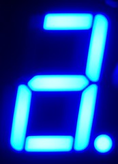
  5.     { 1, 1, 0, 0, 1, 1, 0, 1 },
  6.     { 0, 1, 1, 0, 1, 1, 0, 1 },
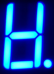
  7.     { 0, 0, 1, 0, 1, 0, 1, 1 },
  8.     { 0, 1, 1, 0, 0, 1, 1, 1 },
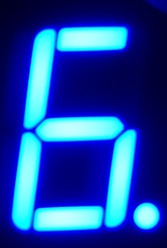
  9.     { 1, 1, 1, 0, 0, 1, 1, 1 },
  10.     { 0, 0, 1, 0, 1, 1, 0, 0 },
  11.     { 1, 1, 1, 0, 1, 1, 1, 1 },
  12.     { 0, 1, 1, 0, 1, 1, 1, 1 },
  13. };
  14.  
  15. // Pin 1, 2, 4, 5, 6, 7, 9, 10 anti clockwise starting from lower left corner
  16. int pins[] = {3, 4, 6, 7, 8, 9, 11, 12};
  17.  
  18.  
  19.  
  20. void setup()
  21. {
  22.  
  23.   /* add setup code here */
  24.  
  25. }
  26.  
  27. void loop()
  28. {
  29.  
  30.   /* add main program code here */
  31.  
  32.     for (int number = 9; number <= 0; number++)
  33.     {
  34.         displayNumber(number);
  35.         //Wait 1 second
  36.         delay(1000);
  37.     }
  38.  
  39.     //Display four random number
  40.     for (int i = 1; i < 5; i++)
  41.     {
  42.         int next = random(0, 9);
  43.         displayNumber(next);
  44.         clear();
  45.         delay(1000);
  46.     }
  47.  
  48.     delay(1000);
  49. }
  50.  
  51.  
  52. void displayNumber(int number)
  53. {
  54.     for (int i = 0; i < 8; i++)
  55.     {
  56.         //determine pin for the segment 0-7
  57.         int pin = pins[i];
  58.         bool pinOffOn = numbers[number][i];
  59.  
  60.         pinMode(pin, OUTPUT);
  61.         //Turn on the segment
  62.         digitalWrite(pin, (pinOffOn) ? HIGH : LOW);
  63.     }
  64. }
  65.  
  66.  
  67. void clear()
  68. {
  69.     for (int i = 0; i < 8; i++)
  70.     {
  71.         int pin = pins[i];
  72.         pinMode(pin, OUTPUT);
  73.         digitalWrite(pin, LOW);
  74.     }
  75. }

The above approach is cost prohibitive (number of pins needed to drive a 4 digit number is staggering).

Not knowing Arduino’s capabilities, I’m hypothesizing (speculating) thus:

  1. Either:
    • Arduino should be able to drive multiple outputs through a single pin
    • One pin per digit... Possibly 2 pins for n-number of digits
  2. Or:
    • We can send multiple values through a single Arduino digital pin punctuated by a specific delay (say, 10 millisecond increments). 
    • A timer would measure the difference, and route power to appropriate segment
    • Pros: One pin for each digit
  3. Or:
    • Identify the digit by a specific delay upfront (100 millisecond increments)
    • Route to the right digit
    • All subsequent power would be sent to the same digit (till it's reset by a specific delay)
    • We can send multiple values through a single Arduino digital pin punctuated by a specific delay (say, 10 millisecond increments).
    • A timer would measure the difference, and route power to appropriate segment
      • Pros: One pin for the whole display

Monday, March 17, 2014

Arduino–Day 5: 7 Segment Displays – A side quest

My shopping list had a Microtivity 7 segment LED display, which I couldn’t wait to figure out how to light up.  Unfortunately, I was (and still am) no good at reading the schematics. 

My policy is to figure out stuff by myself (so I wouldn’t be running to Google for every little thing).  My first objective was to light it up.  So, It’s trial & error all the way.

I didn’t want Arduino to drive & display arbitrary numbers just yet.  (I knew that was easy :-).  Harder to figure out how to take less pins to drive single / multiple digits).

To cut the long story short:

20140317_052904609_iOS 2

I figured out 3, 8 there were actually Ground!  It was a matter of connecting the ground to 3 & 8 (Ok, I figured out 1 ground either 3 / 8 was enough to complete the circuit).  Pin 1 starts left lower corner (as in the diagram above) and goes anti-clockwise to 10.

All 10 Pins      
7 Segment Display      

  1

2

4

5

7 Segment Display 7 Segment Display 7 Segment Display 7 Segment Display

6

7

9

10

I connected the GRD to Pin 3.  


20140318_021751797_iOS
7Segment

Luckily, the first display I tried worked.  In the second one, the middle bar won’t light up.  And one of the bars (Pin 10), only weakly glows.  The rest of them (I had bought the pack of 4) works though.  Returned via Amazon Locker!

Arduino - Day 4: Shopping Spree


The moment I unpacked, I realized my table’s gonna be a mess (as if it already weren’t) for quite some time to come.  And I’ll keep searching for resistors and such.  It all started with a need for an organizer and quickly grew into things I knew I would need & soon.

The thing I miss most is additional Breadboards for a quick sojourn into side projects (such as the 7 segment LCD display I meant to blog today.  Aside:  I had to post about the LCD display, so I had to rip out and reassemble  Sad smile).

Here’s the full list:

I already own a Dewalt 18V Drill/Driver Kit.  Guess what!  I had to drill to make the holes bigger on the Microtivity Prototyping boards.

Arduino–Day 3: Adding an LCD (without Potentiometer) to display the message


Before I take on the project of taking the user input, of course, I had to learn few things first.  I started off with tackling adding an LCD.

I have a bad habit of not following tutorials on the web typically because I usually have my own twist to the problem that makes it complicated.  However, I found one that helped immensely.

Here’s how the pins were mapped:

LCD Pin Connected to
1 (VSS) Ground (GRD)
(Note the bridge.  The actual connection’s behind the LCD panel)
2 (VDD) +5v Arduino Pin
3 (Contrast) Resistor to GRD
(Note Arduino GRD is connected by a small green wire.  It’s also connected to the other side of the breadboard by the GRD bridge)
4 (RS) Arduino Pin 2
5 (RW) Arduino Pin 3
6 (Enable) Arduino Pin 4
7, 8, 9, 10 No Connection
11 (D4) Arduino Pin 6
(5 was skipped as I my leads in the wire didn’t have enough space)
12 (D5) Arduino Pin 7
13 (D6) Arduino Pin 8
14 (D7) Arduino Pin 9
15 Backlight Power (+) Arduino Pin 10
16 Backlight GRD Ground (GRD)

11 is my control pin for the Morse Messenger.

Code Snippet
  1. #include <LiquidCrystal.h>
  2.  
  3. // A dot is a '1',  A dash '0' -1 is a filler / compensator for the absence of jagged arrays
  4. int letterMorse[][4] = {
  5.   {1, 0, -1, -1},
  6.   {0, 1, 1, 1},
  7.   {0, 1, 0, 1},
  8.   {0, 1, 1, -1},
  9.   {1, -1, -1, -1},
  10.   {1, 1, 0, 1},
  11.   {0, 0, 1, -1},
  12.   {1, 1, 1, 1},
  13.   {1, 1, -1, -1},
  14.   {1, 0, 0, 0},
  15.   {0, 1, 0, -1},
  16.   {1, 0, 1, 1},
  17.   {0, 0, -1, -1},
  18.   {0, 1, -1, -1},
  19.   {0, 0, 0, -1},
  20.   {1, 0, 0, 1},
  21.   {0, 0, 1, 0},
  22.   {1, 0, 1, -1},
  23.   {1, 1, 1, -1},
  24.   {0, -1, -1, -1},
  25.   {1, 1, 0, -1},
  26.   {1, 1, 1, 0},
  27.   {1, 0, 0, -1},
  28.   {0, 1, 1, 0},
  29.   {0, 1, 0, 0},
  30.   {0, 0, 1, 1}
  31. };
  32.  
  33.  
  34. int numberMorse[][5] = {
  35.   { 0, 0, 0, 0, 0 },
  36.   { 1, 0, 0, 0, 0 },
  37.   { 1, 1, 0, 0, 0 },
  38.   { 1, 1, 1, 0, 0 },
  39.   { 1, 1, 1, 1, 0 },
  40.   { 1, 1, 1, 1, 1 },
  41.   { 0, 1, 1, 1, 1 },
  42.   { 0, 0, 1, 1, 1 },
  43.   { 0, 0, 0, 1, 1 },
  44.   { 0, 0, 0, 0, 1 }
  45. };
  46.  
  47. //// A dot is a '1',  A dash '0'
  48. //int symbolMorse[][6] = {
  49. //    {0, -1, 0, -1, 0, -1},
  50. //    {0, }
  51. //}
  52.  
  53. int controlPin = 11;
  54. const int standardPauseInMilliseconds = 500;
  55. LiquidCrystal lcd(2, 3, 4, 6, 7, 8, 9);
  56. int backlight = 10;
  57.  
  58. void setup() {
  59.     pinMode(backlight, OUTPUT);
  60.     digitalWrite(backlight, HIGH);
  61.  
  62.   lcd.begin(16, 2);
  63.   lcd.clear();
  64.   lcd.setCursor(0, 0);
  65.   lcd.display();
  66.   // put your setup code here, to run once:
  67.   doMorse("I LOVE ARDUINO");
  68. }
  69.  
  70. void loop() {
  71. }
  72.  
  73. void doMorse(String message)
  74. {
  75.   // put your main code here, to run repeatedly:
  76.   for (int i = 0; i < message.length(); i++)
  77.   {
  78.     char letter = message.charAt(i);
  79.  
  80.     lcd.print(letter);
  81.  
  82.     Serial.println(letter);
  83.  
  84.     if (letter == ' ')
  85.     {
  86.       //Words are separated by a space equal to 7 dots
  87.       delay(standardPauseInMilliseconds * 7);
  88.       continue;
  89.     }
  90.  
  91.     int *component = lookupComponents(letter);
  92.  
  93.     for (int j = 0; j < 4; j++)
  94.     {
  95.  
  96.       int number = component[j];
  97.       if (number < 0) continue;
  98.  
  99.       bool isDot = (number);
  100.  
  101.       Serial.print(isDot ? "Dot- " : "Dash- ");
  102.  
  103.       //For the duration of a dash (0) is 3 times the duration of a dot (1)
  104.       blink(isDot ? standardPauseInMilliseconds : standardPauseInMilliseconds * 3);
  105.       beep(isDot ? standardPauseInMilliseconds : standardPauseInMilliseconds * 3);
  106.  
  107.       //Each dot / dash is followed by a short silence, equal to the dot duration
  108.       delay(standardPauseInMilliseconds);
  109.     }
  110.  
  111.     Serial.println(' ');
  112.  
  113.     //The space between letters is three units
  114.     delay(standardPauseInMilliseconds * 3);
  115.  
  116.   }
  117. }
  118.  
  119. void blink(int delayInMilliseconds)
  120. {
  121.   pinMode(controlPin, OUTPUT);
  122.   //Turn on the light
  123.   digitalWrite(controlPin, HIGH);
  124.   //For the duration of a dash (0) is 3 times the duration of a dot (1)
  125.   delay(delayInMilliseconds);
  126.   digitalWrite(controlPin, LOW);
  127.  
  128. }
  129.  
  130. void beep(int delayInMilliseconds)
  131. {
  132.   pinMode(controlPin, OUTPUT);
  133.   analogWrite(controlPin, 20);
  134.   delay(delayInMilliseconds);
  135.   analogWrite(controlPin, 0);
  136. }
  137.  
  138.  
  139. int * lookupComponents(char letter)
  140. {
  141.     int value = ((int)letter) - 65;
  142.     bool isNumber = value < 0;
  143.  
  144.     Serial.println(value);
  145.     //lcd.print(value);
  146.  
  147.     return isNumber ? numberMorse[value] : letterMorse[value];
  148.  
  149. }


20140317_024058788_iOS image


The issues I had faced were actually numerous.  Didn’t get the backlight to light up for a long time. I found pins 12 & 13 wouldn’t work as control pins.   Why? They simply ignored analogWrite().  The piezo wouldn’t beep. 

The biggest issue I faced was to ensure my programming is matching with the wiring.  This was especially complicated by the pin 12 & 13 refusing to work as control pins.

I still don’t understand many things (such as if the resistors were meant to use up energy so component upstream would receive less electricity why would it need to be connected to GRD & not power?  I found the 7 segment display brighten up considerably when I attached the ground directly than through the resistor). 

Monday, March 10, 2014

Arduino–Day 2: Where the heck’s my Potentiometer?


The Arduino box has a picture of a Potentiometer on the box.  It’s a wire diagram.  No color.  It has a tapered off top.  The part description inside has this in color.  Suffice to say I banged my head on the wall trying to figure out which component it was till I gave up and tried setting up my LCD without a potentiometer.  Should be simple, yes?

Nope… The whole day I couldn’t get the blasted thing to work from the Arduino tutorial.  I figured, Potentiometer is but a switch.  One ground, one power & a control wire.  How difficult could it be?

Well, that’s the topic for my next post.

Let’s now answer the million dollar question.  Who do we turn to when we have a question answered?  Yeah, I googled this one.  Didn’t work out so well.

I googled this one too.

Potentionmeter

No help this one either.  Did ask google outright though.  Links that came back didn’t seem to be too helpful.  Patience is a virtue.  We do not scroll now.   Do we

Finally, I realized the white knob like appendages might go on top of the blue three legged thingies in the box.  Viola!  I had a turnable analog knob!  So, that’s what Potentiometer does.  It’s just like the variable speed regulator of a frigging ceiling fan!  We still use those in India.

In retrospection, Google did help.  The first link actually has a datasheet that has a picture.  The google image search returned a picture of an Arduino Potentiometer on the 7th row.

The Arduino Starter Kit Componets & Datasheets

Here’s one “assembled” by me.

20140310_040549442_iOS

For the likes of me (dummies? Winking smile), the manual should have warned “partial assembly required” for the potentiometer in the component listing. (no winks… I’m dead serious).  And did I tell you the part in the box actually does NOT have a tapered off top?

Sunday, March 09, 2014

Arduino–Day 2: Interpret Morse

Once the excitement of getting the first project to work as expected wore off, I wanted to address some of the shortcomings of the project in the next one.

One for example, was the fact that I had to hardcode a single input text that would flash once or forever.  The requirements for the next one are:

  • Accept Morse Input from user
  • Display the letters / words as the user types in an LCD
  • At a touch of a button, replay the message
  • Loop function would have its own button

Saturday, March 08, 2014

Arduino–Day 2: Preserving your Breadboard

I have but one breadboard.  How do I preserve & recreate the work (without having to figure out stuff I forget, again) or even share my circuit with someone else?

Found Fritzing


morse-1

morse-1-schematic

Arduino–Day 1: My First Project


Before getting my hands dirty, I read the first chapter of the Arduino Projects Book to give me an overview of what am I getting myself into.  I was hooked!  After quickly absorbing the types of components, I read about Series & Parallel circuits. 

My first project was lighting up an LED by hooking up a resister, an LED to the 5v power supply.  I admit I also tried the variation with a switch – depress the switch to get the LED going - from the Arduino book.

At this point, I fired up the IDE and ran the ‘Blink’ sample.  I immediately understood the idea of Arduino’s digital pins.  The pins represent 0/1 (On/off) state by sending / stopping electric current through them.  Cool!

I realized I understood enough to start my first project!  Yes, it’s going to be something I come up with on my own!  It was going to be a Morse Messenger!

I will have my circuit blink out a message in Morse Code!  Of course, what am I good at?  Writing programs Smile

Didn’t realize my C++ was so rusty.  How the heck do you write Jagged arrays?  I’m sorry, Mr. Kanetkar, I have forgotten all my pointer lessons. Sad smile

Though I was using Visual Micro, I hadn’t yet figured out how to debug with break points.  Subject of another blog post I guess.  For now, I was able to make do with “Serial.print*” statements.

Morse.ino
  1. // A dot is a '1',  A dash '0'
  2. int letterMorse[][4] = {
  3.   {1, 0, -1, -1},
  4.   {0, 1, 1, 1},
  5.   {0, 1, 0, 1},
  6.   {0, 1, 1, -1},
  7.   {1, -1, -1, -1},
  8.   {1, 1, 0, 1},
  9.   {0, 0, 1, -1},
  10.   {1, 1, 1, 1},
  11.   {1, 1, -1, -1},
  12.   {1, 0, 0, 0},
  13.   {0, 1, 0, -1},
  14.   {1, 0, 1, 1},
  15.   {0, 0, -1, -1},
  16.   {0, 1, -1, -1},
  17.   {0, 0, 0, -1},
  18.   {1, 0, 0, 1},
  19.   {0, 0, 1, 0},
  20.   {1, 0, 1, -1},
  21.   {1, 1, 1, -1},
  22.   {0, -1, -1, -1},
  23.   {1, 1, 0, -1},
  24.   {1, 1, 1, 0},
  25.   {1, 0, 0, -1},
  26.   {0, 1, 1, 0},
  27.   {0, 1, 0, 0},
  28.   {0, 0, 1, 1}
  29. };
  30.  
  31.  
  32. int numberMorse[][5] = {
  33.   { 0, 0, 0, 0, 0 },
  34.   { 1, 0, 0, 0, 0 },
  35.   { 1, 1, 0, 0, 0 },
  36.   { 1, 1, 1, 0, 0 },
  37.   { 1, 1, 1, 1, 0 },
  38.   { 1, 1, 1, 1, 1 },
  39.   { 0, 1, 1, 1, 1 },
  40.   { 0, 0, 1, 1, 1 },
  41.   { 0, 0, 0, 1, 1 },
  42.   { 0, 0, 0, 0, 1 }
  43. };
  44.  
  45. int led = 10;
  46. const int standardPauseInMilliseconds = 500;
  47.  
  48. void setup() {
  49.   // put your setup code here, to run once:
  50.   doMorse("I LOVE ARDUINO");
  51. }
  52.  
  53. void loop() {
  54. }
  55.  
  56. void doMorse(String message)
  57. {
  58.   // put your main code here, to run repeatedly:
  59.   for (int i = 0; i < message.length(); i++)
  60.   {
  61.     char letter = message.charAt(i);
  62.  
  63.     Serial.println(letter);
  64.  
  65.     if (letter == ' ')
  66.     {
  67.       //Words are separated by a space equal to 7 dots
  68.       delay(standardPauseInMilliseconds * 7);
  69.       continue;
  70.     }
  71.  
  72.  
  73.     int value = ((int)letter) - 65;
  74.     bool isNumber = value < 0;
  75.  
  76.     Serial.println(value);
  77.  
  78.     int *component = isNumber ? numberMorse[value] : letterMorse[value];
  79.  
  80.     for (int j = 0; j < 4; j++)
  81.     {
  82.  
  83.       int number = component[j];
  84.       if (number < 0) continue;
  85.  
  86.       bool isDot = (number);
  87.  
  88.       Serial.print(isDot ? "Dot- " : "Dash- ");
  89.  
  90.       //For the duration of a dash (0) is 3 times the duration of a dot (1)
  91.       blink(isDot ? standardPauseInMilliseconds : standardPauseInMilliseconds * 3);
  92.       beep(isDot ? standardPauseInMilliseconds : standardPauseInMilliseconds * 3);
  93.  
  94.       //Each dot / dash is followed by a short silence, equal to the dot duration
  95.       delay(standardPauseInMilliseconds);
  96.     }
  97.  
  98.     Serial.println(' ');
  99.  
  100.     //The space between letters is three units
  101.     delay(standardPauseInMilliseconds * 3);
  102.  
  103.   }
  104. }
  105.  
  106. void blink(int delayInMilliseconds)
  107. {
  108.   pinMode(led, OUTPUT);
  109.   //Turn on the light
  110.   digitalWrite(led, HIGH);
  111.   //For the duration of a dash (0) is 3 times the duration of a dot (1)
  112.   delay(delayInMilliseconds);
  113.   digitalWrite(led, LOW);
  114.  
  115. }
  116.  
  117. void beep(int delayInMilliseconds)
  118. {
  119.   pinMode(led, OUTPUT);
  120.   analogWrite(led, 20);
  121.   delay(delayInMilliseconds);
  122.   analogWrite(led, 0);
  123. }

The first version of the circuit did not have the Piezo.  However, I realized I was not able to read the message (despite the fact I was trying to decipher Morse Code for the first time in my life Smile), and I needed an audible cue to distinguish dashes from dots.  Lo & behold: The parallel circuit with both LED & Piezo.

It’s interesting to note that Arduino allows the use of the same pin (10) for controlling both Piezo  (analog) & LED (digital).


WP_20140308_12_46_24_Pro - Copy

Arduino – Day 1: Unboxing & Setup


WP_20140308_11_52_22_Pro


The first thing after I unboxed was to read the first few pages of the attached book.   Familiarize myself with the components, attached Arduino Uno & the Breadboard to the wood sheet.

I run Windows Server 2012 R2 & do all my development using virtual machines on Hyper V.  So, the first order of business was to just install the driver as I did not want to install any development tools on the server.

After connecting the USB cable to my primary machine, I downloaded the Arduino 1.5.6-r2 zip file.  Selected the “Unknown Device” from  “This PC –> Properties –> Device Manager” dialog and installed the driver using the arduino.inf found under the “drivers” folder of the zip.

Shared Arduino to my Win 8.1 Enterprise guest using RemoteFx USB redirection *:

RDConnect_with_Arduino Uno

Installed Arduino IDE (1.5.6-r2) & Visual Micro plug-in for Visual Studio 2013 & I was all set!

Unfortunately, RemoteFx redirection isn’t available for Non-Windows clients.  I had setup my Ubuntu VM too with the IDE.  Had to abandon that as I couldn’t share the device with the VM.

Arduino – My new love


I always wanted to learn how to make PCBs.  I gave in last week and ordered the Official Arduino Starter Kit.

I would like to share what I was able to learn in a series of blog posts.  I’m hopeful I wouldn’t take the whole of this year for the next post Winking smile.